006 Milling: Example of hole machining trouble
1. Problems related to hole machining
There are surprisingly many problems related to hole machining during cutting.
One of the problems I introduced last time is the lack of instructions due to forgetting the presence of pilot holes and incomplete parts of the tool, but there are many other problems that occur.
This time we will introduce some typical trouble cases.
Please check to see if any of these apply to you before submitting your drawing!
2. Too deep to bend
Basically, a drill is used for drilling holes.
For deep holes, a long drill called a long drill is generally used.
Alternatively, there are cases where deep hole processing machines called gun drills and BTA are used.
In any case, bending is a problem when drilling deep holes.
The deeper the hole and the harder the material, the easier it is to bend.

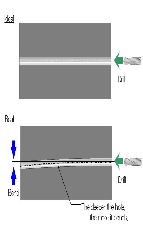
For example, let's consider drilling a deep hole from one side as shown in the diagram above.
The ideal is to drill the hole straight as shown above.
However, in reality, as shown below, the deeper the hole, the greater the bend, and the penetration will shift from the desired position.
In some cases, there may be a deviation of 1 to 2 mm.
This can be a problem when precise hole positions are required.
3. Drilling from both sides
In such cases, drilling form both sides is often performed.

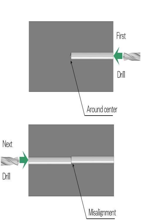
As shown in the diagram above, drilling from both sides is a processing method in which a hole is first drilled from one side to near the center, then a hole is drilled from the other side and penetrated near the center.
This will allow you to drill the holes more accurately on either side.
However, in the case of registration mark processing, a slight difference in level will occur near the center.
This is because not only the hole position itself shifts, but also the hole is bent.
It is necessary to examine whether this level difference is allowable in terms of design.
It would be very helpful at the manufacturing site if you could include notes such as region mark machining is possible'' andlevel difference near the center is allowed within 0.2 mm'' on the drawings.
3. Bulde near the wall
Hole drilling involves using a tool to dig into areas that are originally clogged with material.
Naturally, there is a force pushing outward from the surroundings.
What you need to be careful of is the hole that is close to the wall.

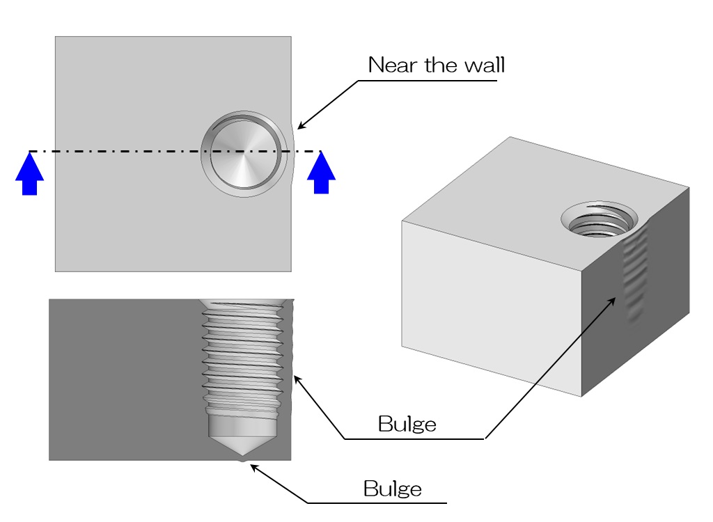
If you drill a hole just close to the wall as shown in the diagram above, a bulge may appear on the wall.
Even if there is some clearance in the drawing, the material will be pushed outwards, creating a bulge.
Alternatively, if you drill the pilot hole all the way to ensure the effective length of the screw, a bulge may also form on the bottom.
I especially want to design holes with enough clearance between them and the walls and bottom.
I think it would be a good idea to allow a grace period of about the radius.

