013 Milling: 3D processing and surface roughness
1. Typical example of 3D processing
This time, we will introduce how 3D machining, which can be said to be the real thrill of cutting, is actually performed.
The finished state has a unique unevenness, and we will also explain the surface roughness.
First, let's think specifically about machining typical three-dimensional shapes.
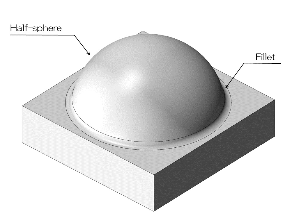
Let's consider a part with a hemispherical convex shape on the base, as shown in the diagram above.
A radius is required at the base.
For machining such three-dimensional shapes by cutting, a ball end mill is used instead of a regular square end mill.
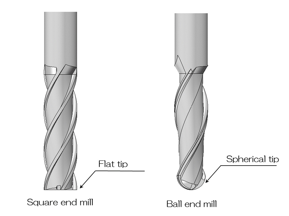
A square end mill is a blade with a flat tip.
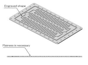
Also called a flat end mill, it can be said to be an end mill that is used for general purposes such as bottom surfaces and steps.
On the other hand, a ball end mill is a cutting tool with a hemispherical tip.
The material is actually cut only in the vicinity of the contact point, and by shifting the position finely, it is possible to form a smooth curved surface.
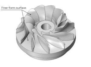
It is used when processing parts with many free-form surfaces, such as molds and aircraft parts.
Even among machining companies, there are many that do not support 3D machining using ball end mills.
2. Flow of 3D processing
Specifically, we will explain how machining progresses using a ball end mill.
Basically, cutting processing is divided into rough processing, which uses a large end mill to create a shape that is close to the finished shape, and finishing processing, which involves cutting accurately to trace the finished shape.
The purpose of rough machining is to remove volume, and the purpose of finishing machining is to achieve final quality and accuracy.
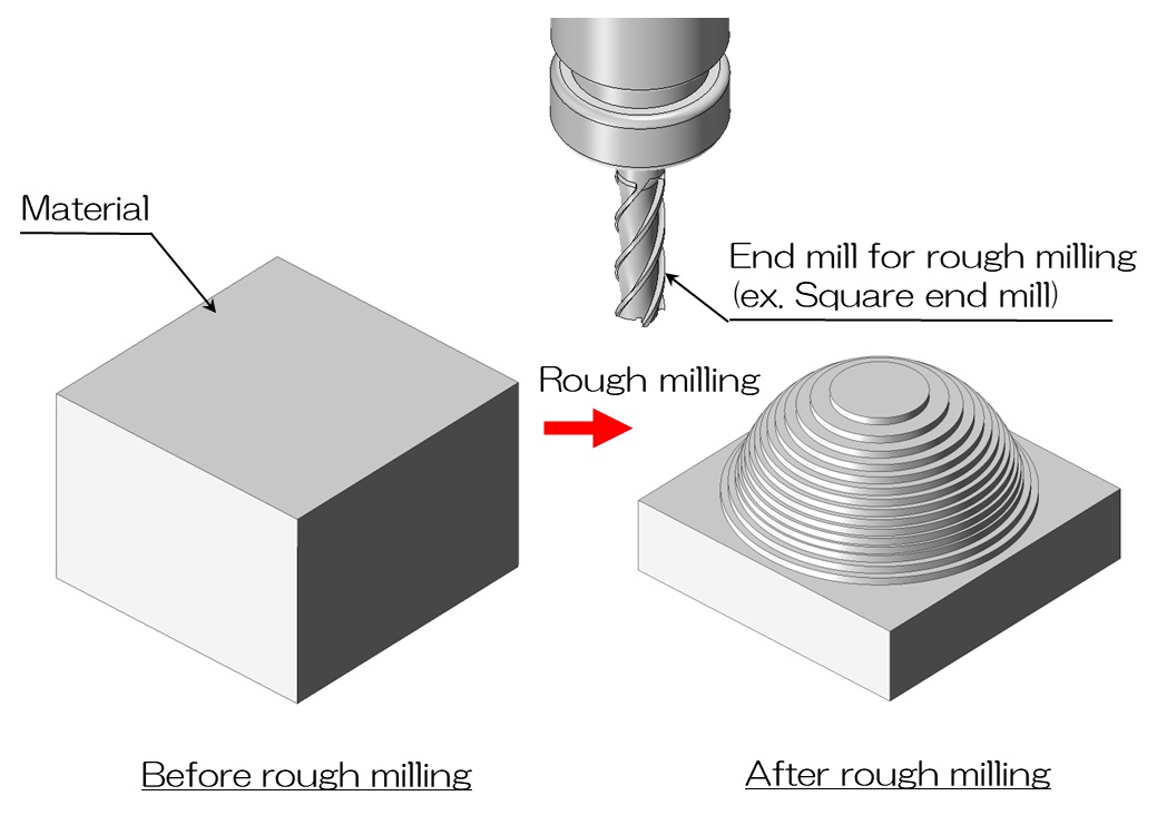
The image above shows rough machining, where a block-shaped material is roughly milled using a rough machining end mill such as a square end mill.
A characteristic feature of using a square end mill is that it creates a step-like jagged appearance.
The purpose of rough processing is to efficiently remove unnecessary volume.
The method chosen is to use a blade as large as possible and process it at high speed without creating a large load during the next finishing process.
In some cases, rough machining may be performed in several stages, using a large knife and then a smaller cutter.
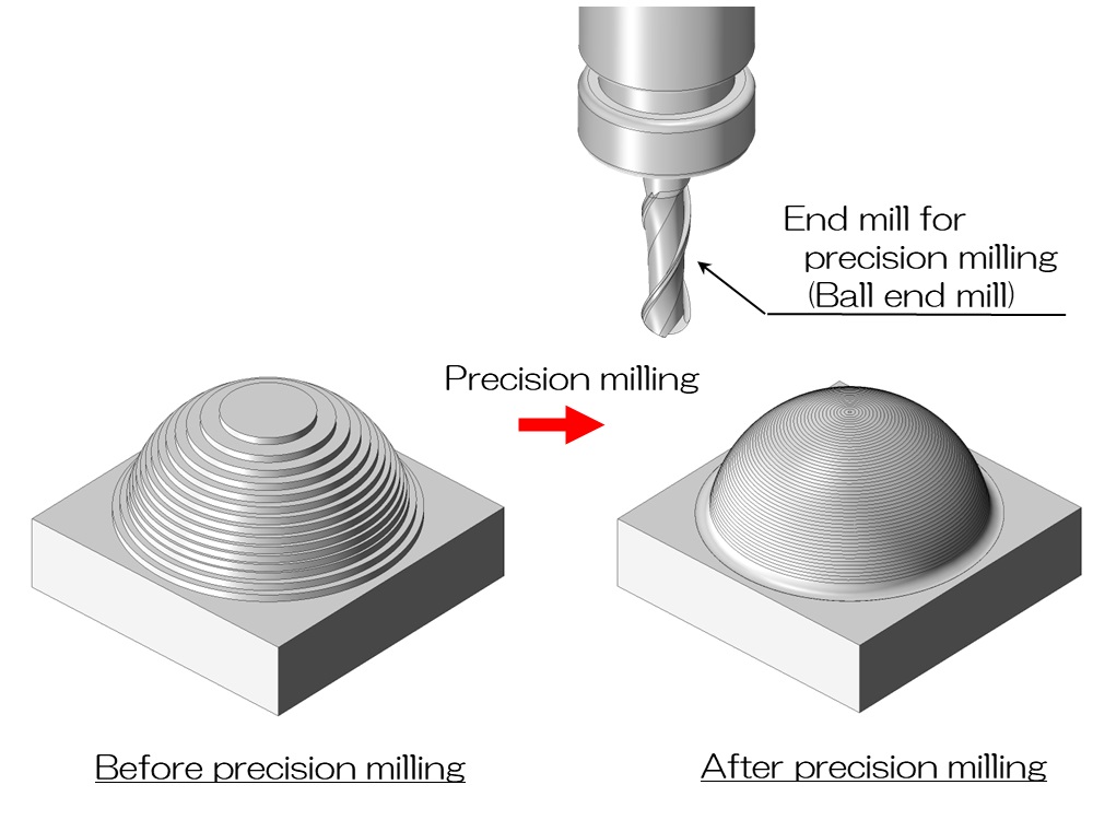
Once the rough machining is complete, the next step is finishing using a ball end mill.
For finishing, finely mill the surface of the final shape with a ball end mill.
While rough machining is a process that removes volume, finishing machining is a process that traces the surface.
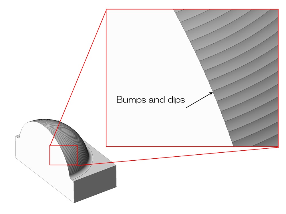
The figure above shows the surface condition after finishing.
If you zoom in, you can see that the arcs of the ball end mill are lined up at a fine pitch.
Even though it is a three-dimensional shape, it does not have a smooth, smooth finish, but rather is covered with minute arc-shaped irregularities.
3D machining can be said to be a method of creating a pseudo-smooth curved surface using a ball end mill.
3. Surface roughness of 3D processing
So, how is the surface roughness calculated when machining a curved surface using a ball end mill?
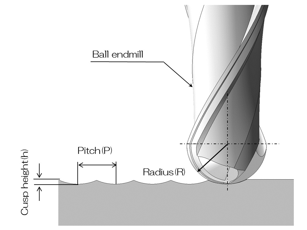
If you enlarge the surface machined by a ball end mill, it will look like the image above.
They are lined up at a pitch with arc-shaped irregularities, and the heights differ between the bottom and surface of the arc.
The height of this unevenness is called cusp height (theoretical machined surface roughness: h).
The following relationship holds between the pitch (P) of a series of circular arcs and the radius (R) of the circular arc (ball end mill).
h = P2 / (8 x R)
In other words, the smaller the pitch and the larger the radius, the smaller the cusp height and the smoother the surface.
Naturally, the finer the pitch, the longer the end mill has to move, which increases machining time.
The larger the radius of the end mill, the less detailed it will be able to cut.
While considering these constraints, the craftsman must decide on the appropriate end mill and processing conditions.
It is best to use an end mill that is as large as possible within the required range.
In reality, you will be constrained by the minimum radius required for the process.
The radius of the end mill will be determined according to this minimum radius.
Furthermore, there is a basic constraint that L/D≦5, so there is a possibility that thin and deep shapes cannot be cut in the first place.
Confirming this before processing is one of the craftsmen's major tasks.
Conversely, if the surface roughness of the curved part is specified, the pitch and radius of the end mill will be calculated and determined from the above diagram.
If the surface roughness is set too finely, it will lead to an unexpected increase in machining time, so please be careful when designing.