016 Milling: The best way called design change!
1. Common distortion
Milling is an important processing method indispensable for manufacturing precision parts.
On the other hand, due to the nature of removing unnecessary parts, it is a processing method that tends to cause deformation due to stress.
This time, we will share typical examples of deformation due to processing and the concept of design changes to reduce deformation.
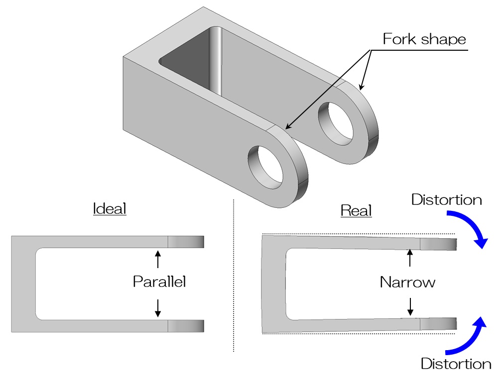
You often see parts with a bifurcated shape (also called a fork shape) like the one shown above.
It is used in applications where it is connected to a mating part by a shaft, etc., allowing it to rotate.
The mating part is inserted into this two-pronged gap, and it is important that the inner sides are parallel so that it rotates smoothly, and that the distance between them is accurate.
However, if you create a design like the one shown above, for example to reduce weight, without taking into account deformation due to processing, the product will inevitably deform to close the gap, making it unusable.
Problems caused by the deformation of bifurcated shapes like this are a typical example that often occurs in cutting operations.
Although it is possible to reduce the amount of deformation at the manufacturing site, the most effective method is to revise the design so that deformation is less likely to occur.
Please try incorporating design ideas to reduce the amount of deformation, such as reducing the amount removed, increasing wall thickness, and adding reinforcement.
For example, how about a design like the one shown below?
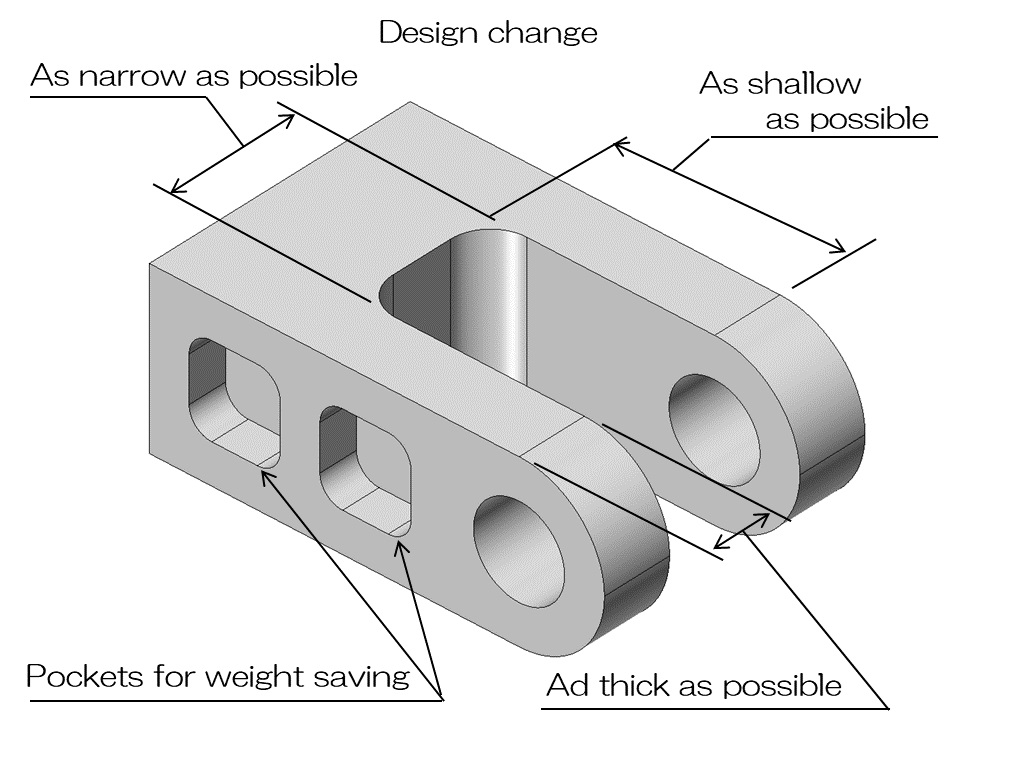
As in the example above, the deformation should be reduced considerably by making the gap between the two forks narrower or shallower to reduce the amount of removal, or by increasing the thickness.
If you are concerned about the weight increasing as the shape becomes thicker, it is a good idea to add some lightening to the extent that does not affect the thickness.
I believe that if you keep this kind of design change in mind, you will be able to avoid unexpected problems in advance.
2. Be careful of the slotted holes near the wall!
In addition to the bifurcated shape, it is necessary to design various shapes that take deformation into consideration.
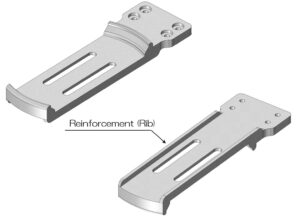
A typical example is a long hole near the edge.
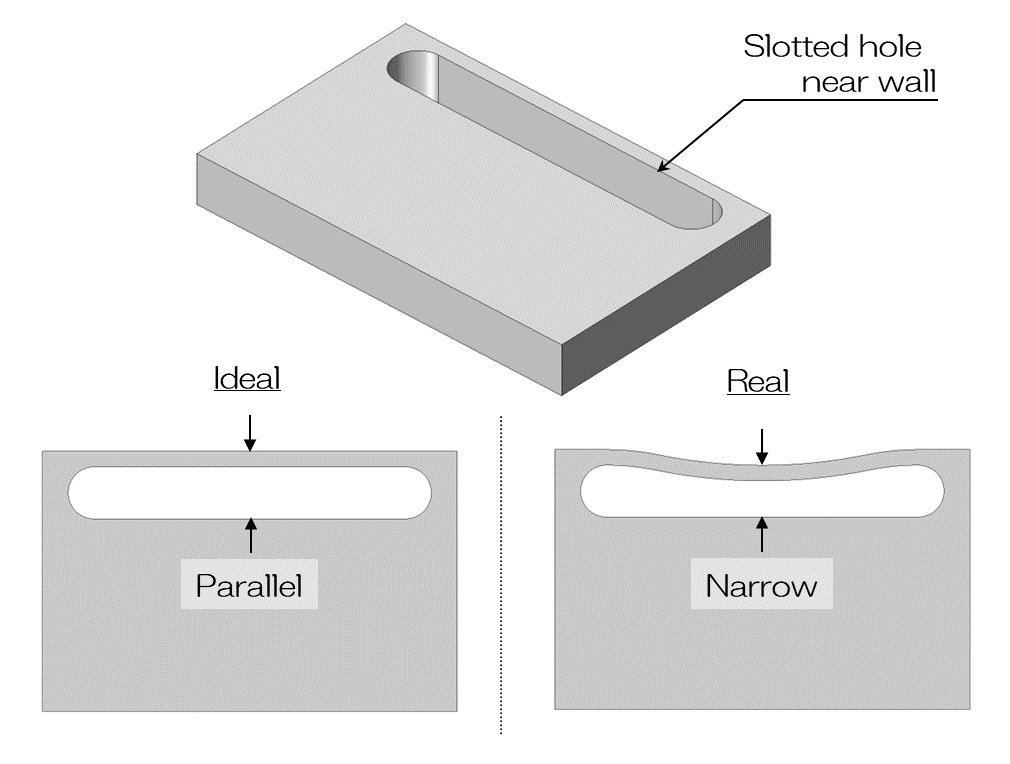
It is also common to see parts with slotted holes on the edges, as shown in the picture above.
I think it is often used to insert a pin and use it as a slide guide, but if it is too close to the edge, the edge will become depressed inward and the groove will become narrower, as shown on the right in the image above. .
If you do that, you won't be able to make it work as designed.
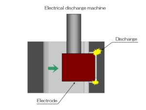
It is possible to suppress deformation to some extent by using wire cutting instead of machining, but it will still deform to some extent.
After all, it is important to respond by changing the design.
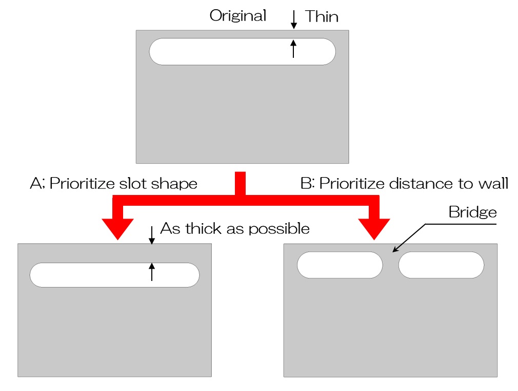
As an example of a design change, if a long hole shape is prioritized, it would be desirable to increase the thickness of the rim, as shown on the left side of the diagram above.
This alone should significantly reduce the amount of deformation.
If the distance from the edge is a priority, please consider adding a reinforcing shape as shown on the right side of the above figure.
I think there are many cases where this is not permissible due to the original intent of the long hole, but if it is permissible, deformation should be considerably suppressed.
There are limits to how much deformation can be reduced at the manufacturing site, so if you take deformation into consideration in your design in advance, the manufacturing process can proceed smoothly.
Please be especially careful when using thin items, items that require a large amount of removal, or items with slotted holes near the edges.