010 Milling: Design considering with setup changes
1. Plate design example
Milling can be said to be a powerful processing method that can achieve high-precision processing.
In recent years, automation has progressed, and machining centers and other machines have added automatic tool exchange functions, reducing the need for operator intervention.
However, when changing the machining surface, setup changes occur, which increases machining man-hours and deteriorates accuracy.
This time, we will explain some tips for designing with this setup change in mind.
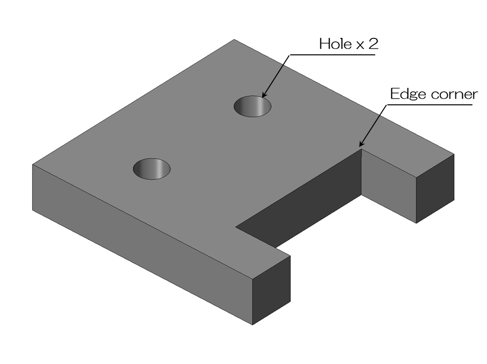
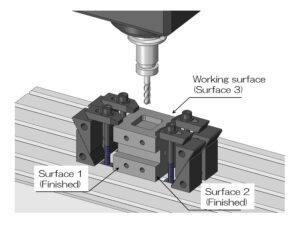
Let's consider the case where a plate like the one shown above is manufactured by cutting.
This plate has two holes and a notch with a pin angle.
Since cutting always creates a rounded shape using an end mill, is this pin angle impossible to achieve?
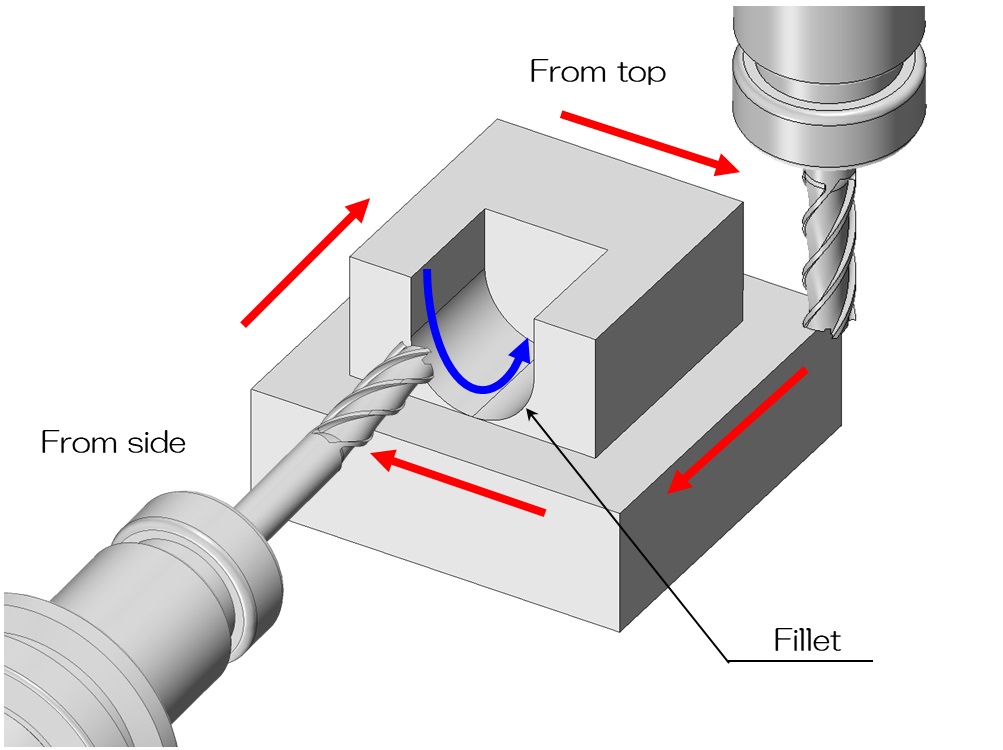
2. Edge shape processing by setup change
In fact, with a shape like this, a square pin shape can be achieved by changing the setup.
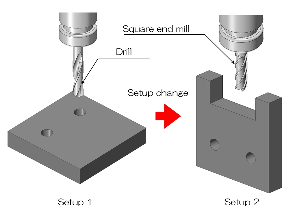
As shown in the diagram above, first drill the hole in setup 1, change the setup, and then change the tool to machine the notch shape.
Just use the corner of the end mill to cut off the corner of the pin.
By doing this, it is possible to create a notched part, but since setup changes will occur, the number of machining steps will increase accordingly.
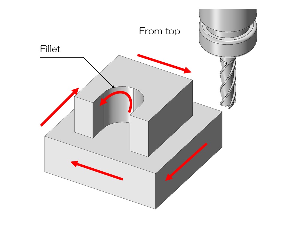
3. The idea of aligning the machined surfaces
This plate can be realized by changing the setup.
However, is this notch really necessary to have a pin angle?
It is OK if it is necessary for the design, but if there is no particular need for the pin angle, there is room for the following ideas.
What will happen if we allow a radius at the corner of the notch as shown in the diagram above?
If you do this, you can machine the holes and notches in the first setup.
There is no need to change setups.
Generally, machining is easier if the corner radius is allowed as shown on the left.
Since the mating part will fit, if you do not want the inner radius to interfere, it is a good idea to attach a nigashi as shown on the right.
Some veteran craftsmen prefer to change the original setup and process the pin angle rather than making such design changes because it is faster, so if you are in doubt, please consult the manufacturing site. .
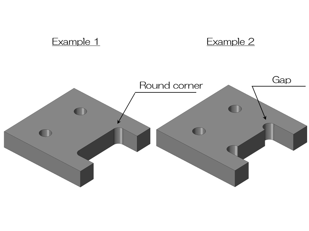
4. Design considering with setup change
Let me introduce another example of a design that takes setup changes into consideration.
The example in the figure above shows that the direction in which the radius is added changes whether a setup change is required or not.
They have almost the same shape, but the direction of the radius of the indentation on the protruding part is different.
On the left side, the direction of the radius is not aligned with the machined surface on the outer periphery.
After machining the outer periphery from above, it is necessary to change the setup and machine this recessed part.
On the other hand, on the right side, the radius is oriented so that it can be processed from above.
By doing this, you can process in one setup without having to change setups.
Even a small difference can make a huge difference in the number of man-hours required at the manufacturing site.
This time I will explain a typical example, but there are many design cases where this kind of innovation can be used.
If you try to reduce the number of setup changes by reducing the number of machining surfaces as much as possible, this will lead to a reduction in machining man-hours, so please consider this.