011 Milling: Actual setup work
1. What is setup work?
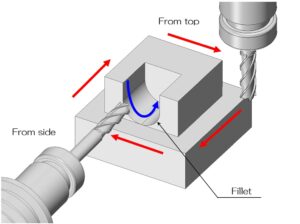
Milling is an indispensable processing method for manufacturing high-precision machined parts.
Furthermore, it is also a method that is becoming increasingly automated, such as automatic operation using NC programs and automatic tool exchange using ATC.
In fact, it is not true that craftsmen do not have to do anything.
The cutting process itself is done automatically, but the preparation work that precedes it is the work of craftsmen.
In the future, setup work may become automated, but currently setup work is a process that requires craftsmanship and affects machining accuracy.
Here, we will introduce typical work examples to give you an idea of how difficult setup work is.
Setup work mainly consists of the following steps.
1. Clamping the workpiece
2. Parallel alignment
3. Coordinate settings
4. Tool installation, length measurement
5. Creation of NC program
2. Clamping the workpiece
The first step in setup work is to clamp the material (workpiece) to the cutting machine.
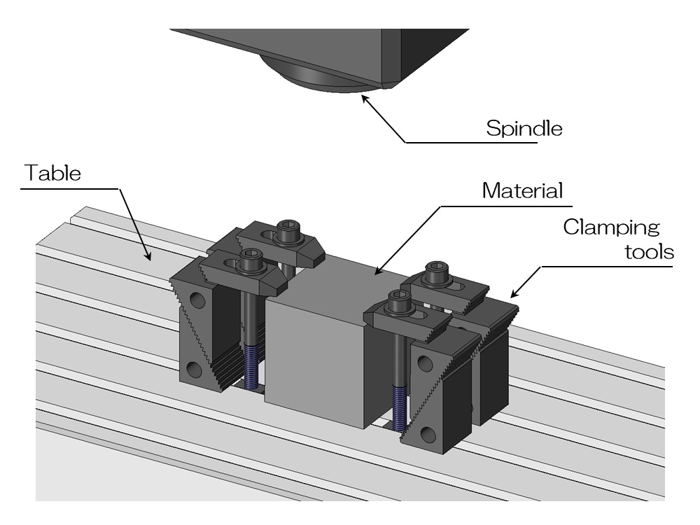
The above figure is a typical example of fixing a block-shaped workpiece directly to a table using a clamp tool.
In addition to using a clamp tool like this, various fixing methods are used depending on the shape and processing content, such as using a precision vise, scroll chuck, or jig plate.
It would be a problem if even a small amount of foreign matter, such as chips, was caught between the table and the workpiece.
In the field of precision machining, which requires accuracy of about 0.01 to 0.1 mm, cases often occur where a foreign object of several mm is caught and the machining dimensions become incorrect, resulting in failure.
Before placing the work, it is necessary to carefully clean the table surface and the bottom of the work.
At this point, you cannot tighten the clamp tool as much as you want to secure it.
First, lightly secure it with temporary tightening.
This is because it is necessary to align the direction of the workpiece with the machine axis.
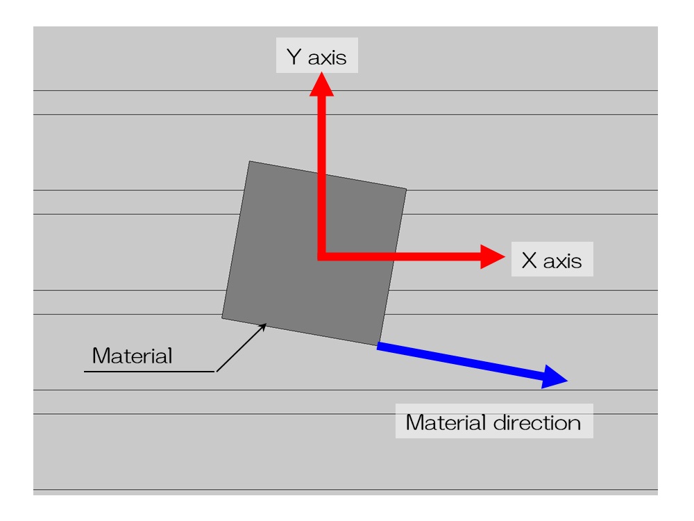
When the workpiece is temporarily tightened, the orientation of the workpiece and the machine axis do not exactly match.
In extreme terms, the situation will look like the one shown above.
The spindle and table can only move based on the X-axis, Y-axis, and predetermined mechanical axes.
Accurate machining cannot be achieved unless the direction of the workpiece matches the machine axis.
3. Parallel alignment
The process of aligning the workpiece with the machine axis is called parallelization.
Test indicators come into play at this time.
Test indicators are also called pick gauges.
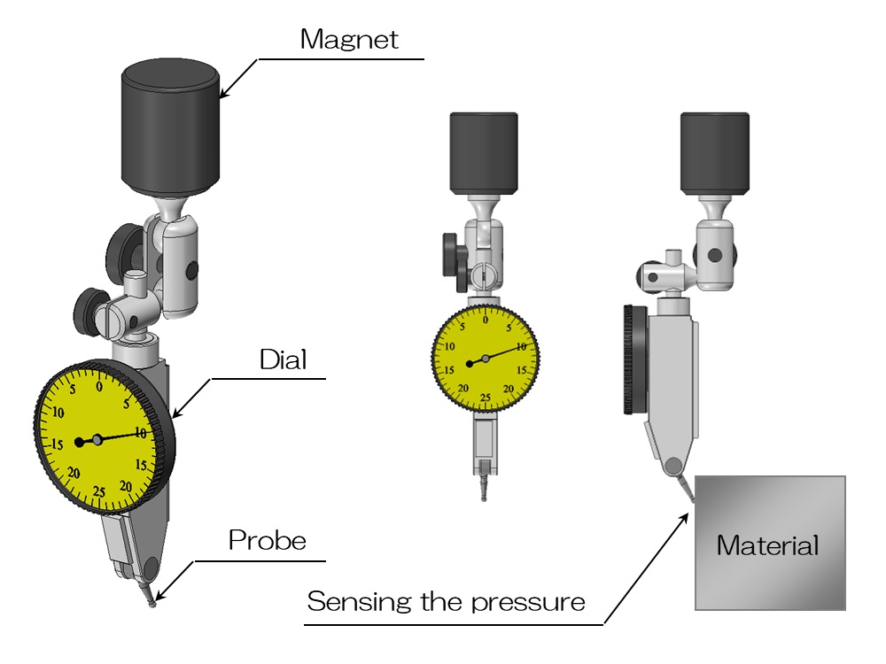
The figure above shows the appearance of the test indicator.
The test indicator consists of a probe, dial, and magnet, and is a general-purpose measuring tool that can be used in a variety of situations other than parallel alignment.
A pressure element is built into the measuring tip at the tip, and the mechanism is such that it detects the amount of pressure applied to the workpiece, etc., and the dial's memory moves accordingly.
Dials with a scale of 0.01 mm are generally used, but 0.001 mm are sometimes used for precision machining.
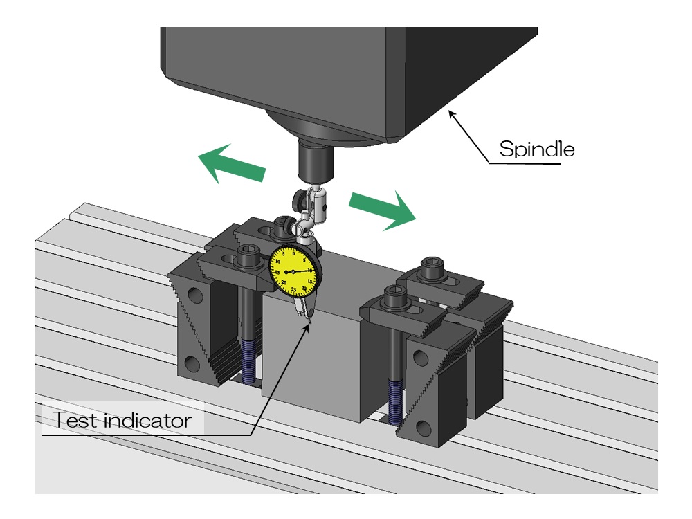
By attaching the magnetic part to the main shaft, this test indicator can be moved in conjunction with the main shaft.
During parallel alignment, press the probe of the test indicator against the side of the workpiece and move it to measure the amount of deviation.
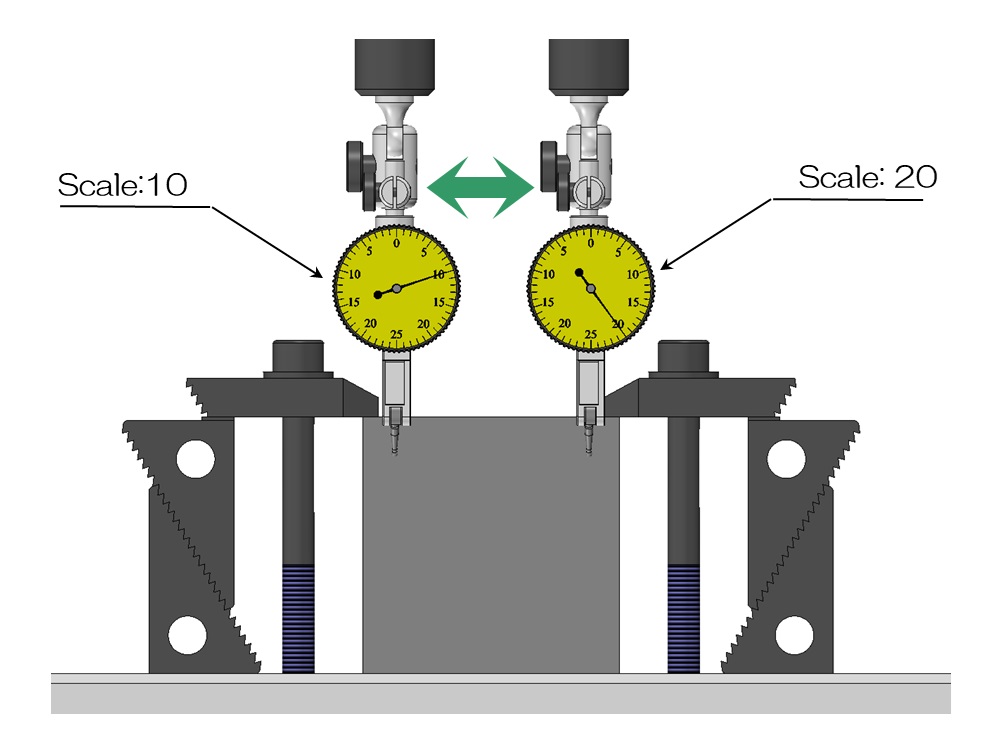
For example, suppose the dial moves as shown in the diagram above as a result of measuring parallelism.
The left side has 10 memory and the right side has 20.
Indicates that the workpiece is tilted with respect to the machine axis by a difference of 10 minutes.
If the test indicator is 0.01mm per division, it means that it is tilted by 0.1mm in 10 divisions.
Parallel alignment is the adjustment of this inclination.
Specifically, the craftsman makes adjustments by lightly tapping the right side of the workpiece with a plastic hammer.
This is a world that still requires analog adjustments.
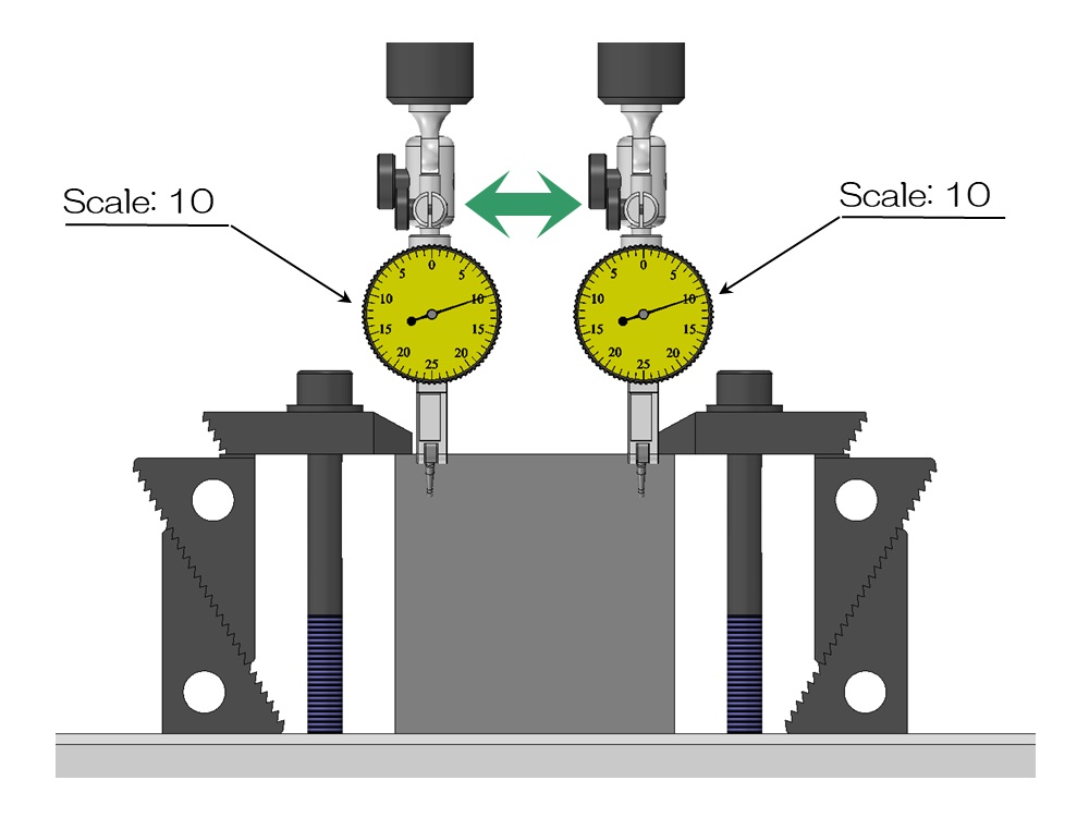
After hitting with a hammer, move the test indicator to check the amount of deviation, and if the adjustment is not sufficient, hit again and repeat the adjustment until the accuracy is within the required range.
Then, when the amount of deviation falls within a certain range as shown in the diagram above, fully tighten the clamp tool to completely secure the workpiece.
Of course, there is a possibility that some deviation may occur after final tightening, so check the inclination with a test indicator even after final tightening.
In this example, the workpiece is placed directly on the table surface, which is parallel to the height direction.
We only checked the parallelism of the XY plane during parallel alignment, but if you are fixing it with a precision vise, you may also need to check and adjust the parallelism of the XZ plane in the direction of inclination.
Up to this point, workpiece fixing and parallel alignment are completed.
4. Setting the machining origin
Now, the workpiece is fixed parallel to the machine.
The next step is to accurately input the position of this workpiece into the machine.
To do this, it is necessary to accurately measure the workpiece's machining origin from the machine coordinate system.
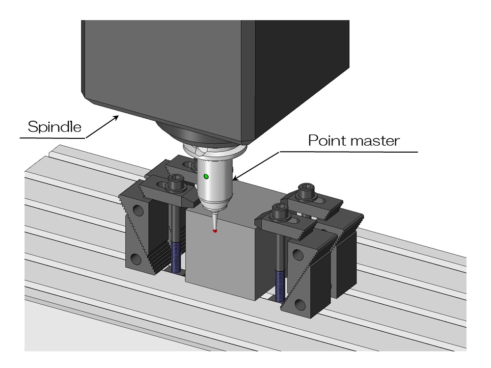
A measuring tool called Point Master is used in such cases.
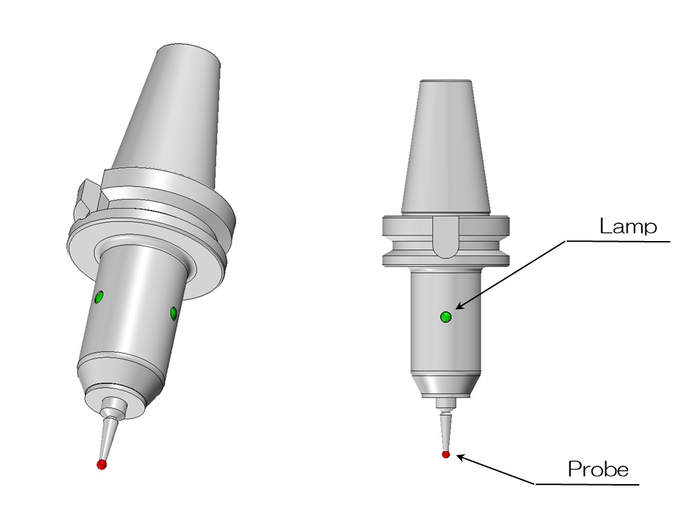
The figure above shows the appearance of Point Master.
A probe is attached to the tip to detect contact with an object.
When touched, a lamp lights up and some make a beeping sound.
This time, let's set the workpiece's machining origin at the center of the X-axis and Y-axis.
When using the Point Master to measure the origin, first attach the Point Master to the spindle and rotate it at low speed.
By doing this, the contact position of the point master will be the same as the X-axis and Y-axis coordinates of the main axis.
(Strictly speaking, it shifts by the radius of the probe)
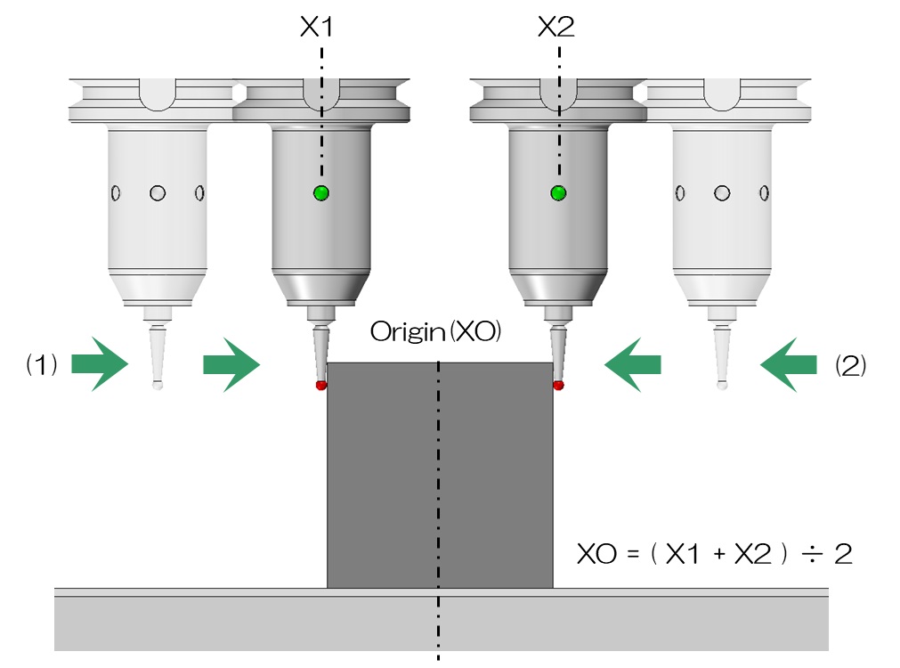
Let's take a look at the steps to set the origin in the X-axis direction.
First, slowly bring the Point Master closer to the workpiece from position (1).
Then, when the probe contacts the side of the workpiece, record its position (X1).
Next, move the point master to position (2) and bring it into contact with the workpiece from the opposite side.
Then, the contact position (X2) is recorded.
Then, we can see that the center coordinate that divides X1 and X2 in the machine coordinate system is the X coordinate of the workpiece's origin.
If you measure the Y-axis direction in the same way, you can determine the machining origin X and Y.
Input this position to the processing machine to complete the setting of the processing origin.
5. Installing and setting tools
Now that the workpiece is fixed and the origin has been set, the next step is to install and set the tool (end mill, etc.).
End mills come in a variety of types and sizes, and the appropriate one is selected and attached to the machine for each machining process.
The most important thing is the type of tool, its diameter and length.
In particular, the overhang length cannot be determined exactly before it is installed on the machine, so it must be measured on the machine.
This is also a very important task to determine the position in the height direction (Z).
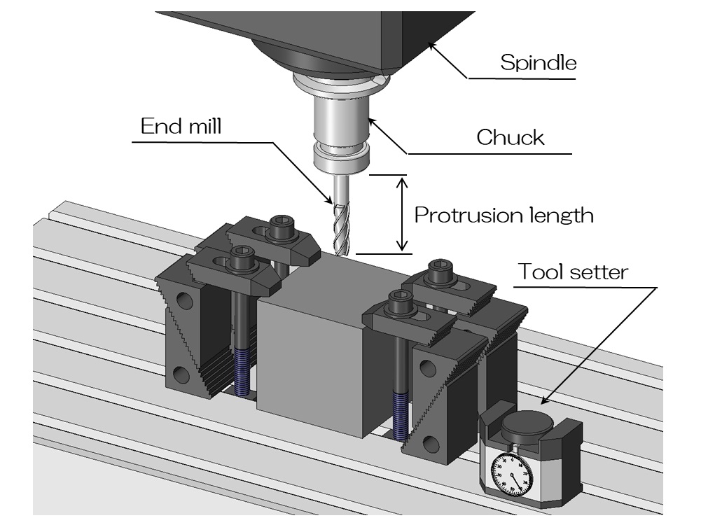
First, secure the tool to be used with sufficient protrusion, secure it to a tool called a milling chuck, and attach it to the spindle.
If the overhang is long or high machining accuracy is required, place a test indicator on the side of the tool and rotate the tool to check the runout.
If the tool is shaking a lot, remove the tool from the milling chuck, clean it, and then reinstall it.
If the runout is at a level that does not cause any problems, measure the length.
Cutting machines control the center of the spindle and the position of the tool tip.
Measure how high the tip of the tool is above the table surface and enter the setting value into the machine.
This work is called length measurement.
This is a very important process because if the length measurement is not accurate enough, the height of the machining will be off by that amount.
Also, setting the wrong digit for the tool height can cause a serious accident such as the tool hitting the workpiece or table during machining, so length measurements must be taken carefully and accurately. not.
If machining is performed using a machining center, multiple tools can be set together and stored in a tool magazine, so set the necessary tools here.
At this point, the preparation work on the machine side is finally complete.
6. Creating and inputting NC programs
For simple machining using a general-purpose milling cutter or NC milling cutter, the tool is then rotated and the craftsman directly operates the machine to proceed with the machining.
On the other hand, in the case of NC machining, an NC program is created to automatically move the machine and input into the machine.
NC machining means machining using numerical control, and means that the machine automatically processes according to a program based on coordinate values.
The program for this purpose is the NC program.
NC programs are created by combining commands to control machine behavior, such as G codes and M codes, and coordinate values for the tool tip.
Commands include starting and stopping tool rotation, moving the spindle and table, turning on/off cutting fluid discharge, and changing tools.
If this NC program is simple, it may be entered by the craftsman himself using the on-board control device.
Also, it seems that there are some that allow you to create some advanced NC programs on the control device side.
If a more advanced and complex NC program is required, it can be created using an application called CAM (Computer Aided Manufacturing), and the data can be input by transferring it to the machine.
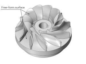
CAM-based NC program creation is used for 3D machining and 5-axis machining.
We will explain the NC program in detail in another article.
At this point, the setup work is finally complete.
This setup work occurs every time a setup change occurs.
Even though automation is progressing, many people may be surprised to find out that there is still a surprising amount of work that is done by craftsmen.
Automation may progress further in the future, but there is no doubt that this is a field that still requires the intuition and skills of craftsmen.