003 Milling: Corner radius and L/D
1. Corner radius inherent in milling process
Milling using milling machines is the star of precision machining.
A block-shaped material (also called a workpiece) is fixed to a machine and cut by rotating a cutting tool called an end mill.
Precision parts that require dimensional accuracy such as ±0.02mm are mainly subjected to this milling process.
However, it is true that there are various restrictions because rotating tools are used.
The quality of the drawing will differ greatly depending on whether you know this constraint in advance or not.
This time, we will explain corner radius and L/D among the characteristics of cutting processing.
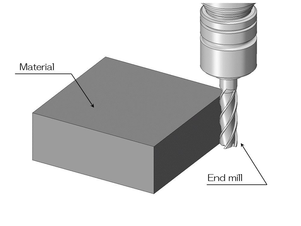
In the milling process, a rotating end mill is operated automatically by an NC program or by a craftsman's handle operation, and the parts that collide with the material are removed.
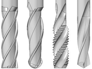
There are various types and sizes of end mills, including the general square end mill (a flat-bottomed blade like the one shown above), a ball end mill with a hemispherical tip, and a roughing end mill suitable for secondary cutting.
In both cases, the tool rotates to cut the material, so there are limitations unique to this method.
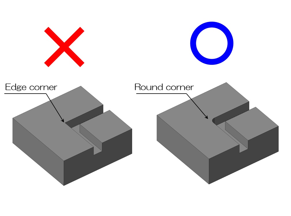
For example, let's say you dig a groove by moving the end mill in an L-shape as shown in the diagram above.
Then, of course, the bent part will not have a pin angle like the one on the left.
In reality, the rounded shape remains on the outside by at least the radius of the end mill.
Because a rotating tool is used, this type of rounded shape is formed, which is a characteristic of cutting processing, and is a major constraint in terms of design.
2. Pocket shape and corner radius
Milling is also often used for parts that need to be made lighter, such as aircraft parts and race parts.
In order to achieve precision and make it as light as possible, it is common practice to remove as much meat as possible from unnecessary parts.
This type of shape is also called a pocket shape, and the machining of a pocket shape is also called pocket machining.
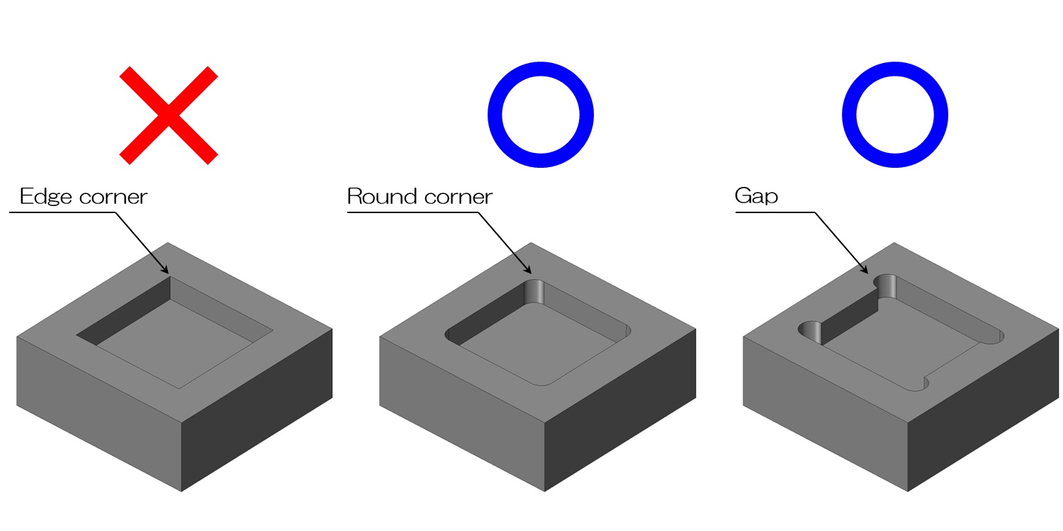
The four corners of the pocket shape do not have pin angles like the one on the left in the image above.
As expected, the four corners are rounded like the center.
If a pin angle is absolutely necessary, you can aim for the pin angle as much as possible using die-sinking electric discharge machining, but this increases machining costs and construction time.
This is because die-sinking electrical discharge machining begins with designing and manufacturing the electrode itself necessary for machining.
It is not very rational to design the pin angle by force.
The idea we came up with at such times was a shape called nigashi.
It is used when the convex shape of the other party fits accurately into the pocket.
The four corners are not radiused on the inside, but rounded on the outside by the radius.
By doing this, the pocket shape can be precisely finished by cutting, and the remaining straight part will be used for fitting with the other party.
3. Corner radius of notch shape
Along with pocket shapes, notch shapes are often used in cutting processes.
The notch shape is not surrounded by walls except for the top surface like a pocket shape, but is open on 2 or 3 sides.
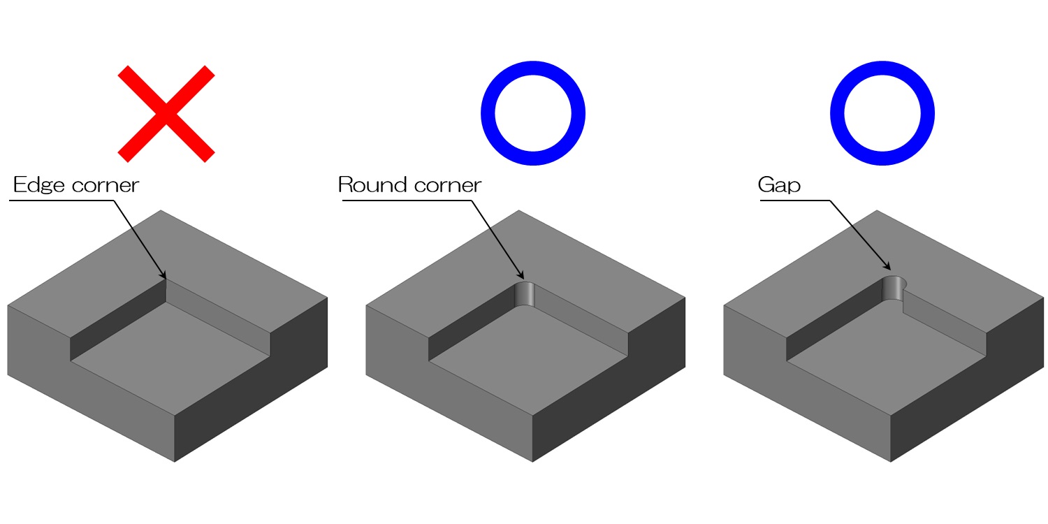
The image above is an example of a typical cutout shape with three walls.
Similar to the pocket shape, the pin angle shown on the left cannot be achieved by cutting.
It will either have an inner radius like the one in the center, or a bittern shape like the one on the right.
In fact, it is possible to approach the notch shape from the open side with an end mill and create a rounded shape in the direction shown in the diagram above.
Although it is not very common, knowing that such processing can be done will increase the degree of freedom in design.
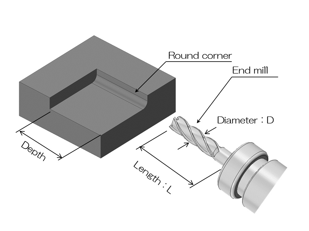
4. What is L/D?
I hope you understand that cutting processes involve rounded shapes.
How common is this are?
From a designer's point of view, you might think that it would be best to use an end mill with a small radius to minimize the radius.
In fact, there are important restrictions on the size of the corner radius and the depth of the shape.
The end mill rotates at high speed and collides with the material while rotating.
At that time, if the end mill protrudes too long and thin, the tip will become unstable under the load of machining.
A rough cutting surface called chatter may form, or in the worst case, the end mill may break during machining.
Basically, the diameter (D) of the cutter and the protrusion length (L) of the cutter are constrained as shown in the formula below.
L/D≦5
In other words, the protrusion length of the cutter is up to 5 times the diameter of the end mill.
Cutting depth = overhang length, and the diameter of the end mill is twice the corner radius.
Please understand that from a designer's perspective, there is a limit to the cutting depth being 10 times the corner radius.
However, this is not necessarily true due to material, shape, processing conditions, etc., so it is only a guideline.
If you are having trouble with a last-minute design, please feel free to contact the manufacturing site.