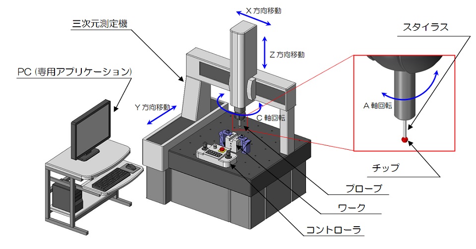
What is a coordinate measuring machine (CMM)?
A Coordinate Measurement Machine (CMM) is a precision measurement machine equipped with a mechanism that drives the X, Y, and Z axes.
The tip of the head is equipped with a probe for measurement, and by touching the tip of the probe to the product, the three-dimensional coordinates of the point of contact are recognized and recorded.
By measuring the coordinate information of various points, it is possible to determine the plane, diameter, etc., and even calculate the positional relationship between shapes.
This makes it possible to measure geometric tolerances that cannot be measured with general-purpose measuring instruments.

Coordinate measuring machines are very expensive and require specialized skills to perform measurements.
In addition, to maintain measurement accuracy, it must be used in a space with constant air conditioning (approximately 20 ± 1 degrees Celsius, etc.), and it must be installed on a ground with low vibration and high rigidity.
Elements measured by CMM
With a three-dimensional measuring machine, you set the expected element and then measure the points used to confirm that element.
Each element and the minimum number of points required to confirm that element are as follows.
| Element | Minimum number of point | Measured value |
|---|---|---|
| Point | 1 | Point data (Coordinate value of point for X,Y,Z) |
| Line | 2 | Line data (Vector and coodinate value of any point on the line) |
| Plane | 3 | Plane data Normal data |
| Circle | 3 | Diameter, Radius Roundness Coodinate value of center point |
| Ellipse | 5 | Ellipse data Long side / short side length Coodinate value of center point |
| Sphere | 5 | Diameter, Radius Sphericity Coodinate value of center point |
| Cylinder | 6 | Center line data Diameter, radius Cylindricity |
| Cone | 6 | Center line data Diameter, Radius |
During actual measurement, the information calculated from these elements is combined and a dedicated application is used to obtain numerical values for the items required for inspection.
Geometric tolerances can be determined not only from the results of each element, but also from the three-dimensional positional relationships between the elements.
For example, it is possible to perform tests such as obtaining coaxiality from the measurement results of two cylindrical shapes or obtaining perpendicularity from the measurement results of two surfaces.''
The number of points required to determine each element is shown in the table above, and the measurement accuracy improves as the number of points increases.
Normally, approximately 8 to 20 points are measured to measure a circular shape of Φ50 mm.
However, acquiring more points than necessary not only does not improve measurement accuracy but also increases man-hours.
A veteran inspector's skill is to consider a reasonable number of points depending on the shape.